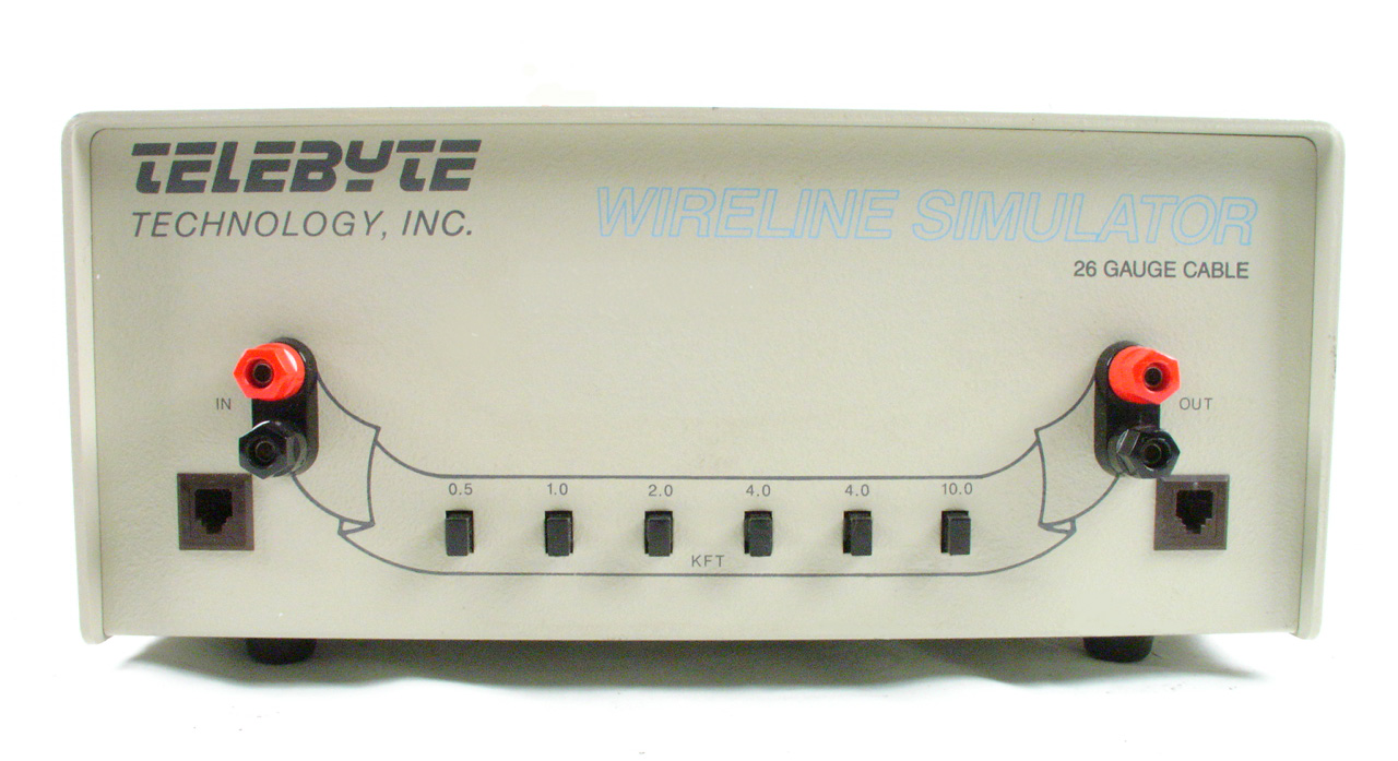
The Telebyte Model 453 Wire Line Simulator is a compact laboratory or field instrument. It precisely simulates the frequency response and propagation delay of a single, 26 AWG (0.4mm), telephone pair from DC up to 1.1 MHz.
This product is intended for developing and testing higher speed local loop transmission products such as ADSL, HDSL, T1 and E1 applications.
The unit contains internal sections representing 500 ft, 1,000 ft, 2,000 ft, 3,000 ft, 6,000 ft, and 6000 ft of cable. These sections can be connected in series by operating six (6) independent push button switches, which allow the user to obtain any length of cable from 0 to 18,500 ft in 500 foot increments.
Termination points are provided at fixed increments to allow for simulation of bridge taps. This arrangement provides a great deal of versatility in modeling complex cable configurations when additional simulators are available.
Bridge taps are improperly matched sections of a cable pair that may be connected in a bridging manner along the length of a wire line, (see Figure 1.) If the wire line is used for data transmission at frequencies well above audio then these improperly matched sections of line may cause interference in the form of echoes, etc. By providing "access" to various points along the cable length the Model 453 can model the effect of bridge taps. This is accomplished merely by connecting additional simulators at these access points.

Figure 1: Bridge Taps
The bridge tap access points are located on a rear mounted 50 pin "Amphenol Series 57" type female connector. A mating male connector must be used to gain access to these points.
The figure below shows the bridge tap locations and associated terminal pair connections in the form of a single line block diagram. Note that the switch associated with the section containing the bridge tap must be activated. For example, if a line having a length of 9 kft is required with a bridge tap at 3 kft, depress the 1, 2, and 6 kft switches and access the bridge tap at terminals 5 and 30 of the 50 pin connector.

Figure 2: Bridge Tap Connections
The unit does not require power and has two bi-directional ports. It will support DC loop currents of up to 120 mA and combined station battery and ringing voltages of up to 175 Volts peak.
The simulator represents a two-wire line. For technologies that require four-wire lines for operation, either two simulators can be used or a single simulator can be connected in conjunction with the telecommunication device configured in a back-to-back arrangement. Figure 2 illustrates both configurations.

Figure 3: Four Wire Operation


